Engineering Case Study
Iterative Electromechanical Design: The HoloDevice Architecture
Project Overview
The HoloDevice project represents a multi-year electromechanical engineering journey, evolving a conceptual video game mechanic into a fully functional, wearable mechatronic system. Originally inspired by the intricate holographic technology of Apex Legends in late 2020, this build progressed through four distinct architectural iterations. The final system seamlessly integrates advanced 3D polymer fabrication, microcontroller packaging, and custom user interface (UI) programming to create a highly durable, performance-ready prop.
Phase 1: Proof of Concept & Rapid Prototyping
The initial iteration served as a rapid physical prototype to test form factor and basic aesthetics.
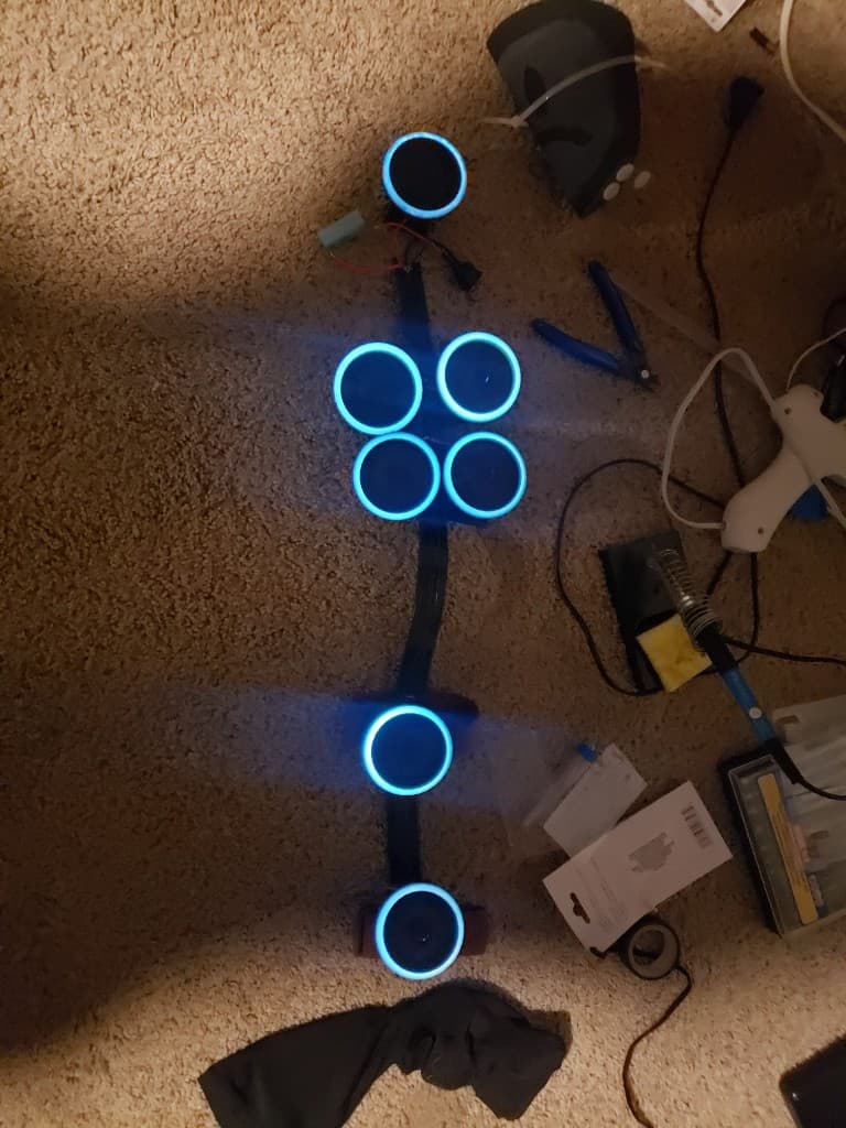
- V1: The original proof-of-concept was rapidly fabricated in a matter of days utilizing painted jar lids.
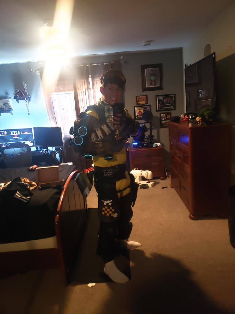
- V2: The system was quickly upgraded using early 3D-printed shells sourced online. This iteration marked the first integration of active hardware, utilizing 12V LED rings controlled by a standard Arduino and a relay shield.
- Initial Wiring: The preliminary circuit was soldered utilizing a repurposed computer charging cord and thin 20 AWG wire.
Phase 2: Failure Analysis & Diagnostics
Field testing the V2 architecture exposed critical vulnerabilities in both the mechanical assembly and electrical routing. Identifying and analyzing these failure points laid the groundwork for a complete system overhaul.
- Mechanical Failure: The V2 chassis relied heavily on hot glue for assembly, which lacked the structural integrity to withstand outdoor environmental conditions and fell apart during use.
- Power & UI Inefficiencies: The system was powered by a heavy 12V battery housed in a back-mounted control box, which only provided approximately one hour of uptime. Furthermore, the primary power switch was located on the back, creating severe user accessibility issues.
- Electrical Hazards: The reliance on thin 20 AWG wire proved insufficient for the power draw, ultimately resulting in a short circuit and smoking components during a convention field test.
Phase 3: Design for Manufacturing (DfM) & Structural Refinement
To solve the critical flaws of V2, the entire mechanical chassis was redesigned from the ground up.
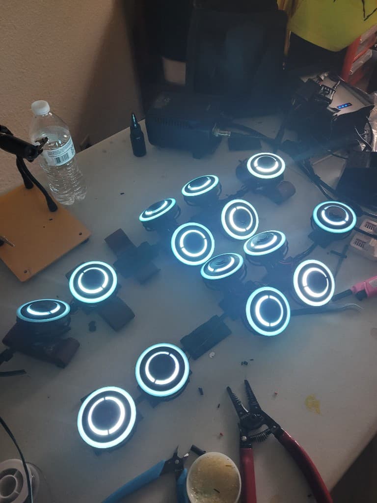
- Mechanical Integrity: Custom 3D models were engineered specifically around the dimensions of the LED rings. The new architecture completely eliminated adhesives, utilizing precision-modeled tolerances for easy printing and secure bolted assemblies.
- Electrical Overhaul: The wiring harness was upgraded to thicker, safer 18 AWG wire to prevent overheating. The heavy 12V battery was swapped for a 12V rechargeable power supply, and modular quick-connectors were added so the control box could be safely tethered after the arm devices were equipped.
- Ergonomic UI: The power switch was relocated from the back-mounted controller directly to a hand attachment, drastically improving user accessibility. This iteration yielded vastly improved battery life and structural survivability.
Phase 4: Micro-Packaging & Advanced Control Systems (Current Architecture)
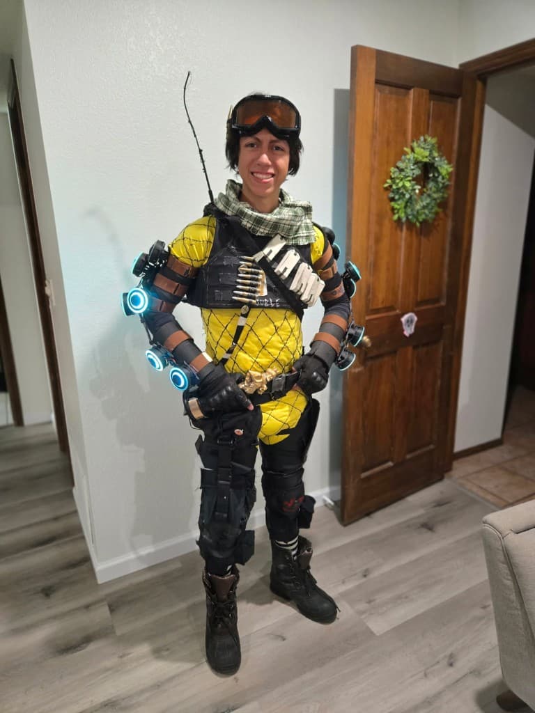
The current iteration (V4) represents the peak of the system's electromechanical optimization, leveraging professional-grade fabrication tools and highly efficient power packaging.
- Hardware Downsizing: The bulky 12V power supply and relay shield were entirely engineered out of the system. The power architecture was optimized to run on a 5V supply driven by an Arduino Nano, significantly reducing the overall weight and footprint of the system.
- Tolerance Optimization: The mechanical enclosures were heavily revised and prototyped in disposable filament before final fabrication. The final parts were designed specifically around the tight tolerances of a Bambu X1 Carbon printer, ensuring maximum impact resistance.
- Custom UI Glove: The basic hand switch was completely replaced with a custom-modeled, wearable control glove. This glove houses four tactile push buttons, allowing the user to actively switch modes, dial in brightness, change colors, and trigger complex LED animations instantaneously during a performance.